Where's LoRa?
Lauren Greenhill (LJG227) and Veda Balte (VB269)
December 10, 2023
Demonstration Video
Introduction
This project features two separate modules. The first module includes a Raspberry Pi, PiTFT, T-Beam Meshtastic, and a camera on a SG-90 gimbal. The T-Beam Meshtastic is a microcontroller integrated with a LoRa transceiver and a GPS. The second module consists of only a T-Beam. A user can place the external T-Beam in some distant location. Then, after traveling a distance away, they can use the Raspberry Pi module to learn about the location of the T-Beam. The T-Beam will constantly beacon LoRa packets with its GPS coordinates. After receiving these coordinates using the LoRa radio embedded in the local T-Beam, the Raspberry Pi module inputs its current location (GPS coordinates obtained by the local T-Beam) and the location of the external T-Beam into a custom GUI to display a map on the PiTFT. It also rotates the camera in the direction of the T-Beam. The user can use the PiTFT side buttons to switch between the map view, input from the camera, and a screen with an arrow pointing in the direction of the external T-Beam.
Project Objective:
Using the Raspberry Pi embedded device, a user shall be able to navigate within 100 meters of the T-Beam based on visual queues displayed on the PiTFT assuming both the Raspberry Pi embedded device and the T-Beam have obtained a GPS lock.
Design & Testing
Initial Design
Our initial design used a RFM95W LoRa Radio connected to the Pi via SPI and a NEO-6M GPS connected to the Pi via serial. This design was fully functional and met all project objectives. During testing, all devices connected to the Pi, including the Pi itself shorted, causing us to switch from using the RFM95W LoRa Radio and NEO-6M GPS to a second T-Beam. Using a second T-Beam as a co-processor allowed us to use the onboard GPS and LoRa Radio modules. Data could then be sent from the local T-Beam to the Pi via a serial connection.
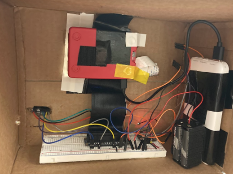
Initial Design Wiring
Initial Design Box
Overall Software Architecture
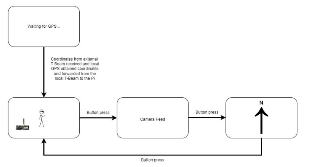
Pi Modes
Our design features four possible displays on the PiTFT, all created using pygame. The first screen is the START screen. This screen is displayed when either the local T-Beam GPS has not received a lock (meaning it has not received location data) or GPS coordinates from the external T-Beam have not been received via LoRa. Once both of these coordinates have been received, the display transitions to the MAP screen. The person icon represents the Pi and local T-Beam module. The person remains fixed on the screen.
dx and dy are calculated using the following formulas from GiSMAP:
dx = cos( external T-Beam latitude ) * sin ( external T-Beam longitude - Pi longitude )
dy = cos( Pi latitude ) * sin( external T-Beam latitude ) - sin( Pi latitude ) * cos( external T-Beam latitude )
*
cos( external T-Beam longitude - Pi longitude )
The T-Beam icon represents the external T-Beam. It is displayed relative to the stationary Pi icon. Since the Pi icon is displayed in the center of the PiTFT, the range of dx and dy are mapped from (-0.005, 0.005) to (-width/2, width/2) and (-height/2, height/2) respectively. These ranges were found by calculating the max dx and dy across Cornell’s campus and would have to be adjusted if the two modules were placed further apart.
There is a callback function linked to GPIO 22, which is one of the PiTFT buttons. When this button is pressed,
the screen transitions between displays. If it is on the MAP screen, it transitions to the CAMERA screen. Using
the PiCamera library capture_continuous function, video at a frame rate of 24 fps is displayed onto the PiTFT.
The
capture_continuous function is blocking, so GPS coordinates are not updated while in this mode. During this
mode,
two variables are used to monitor the desired angle of the servo (old_angle and new_angle). new_angle is
calculated at the beginning of every Pi loop and is also used by the ARROW display mode. It is calculated using
the following formula from GiSMAP:
new_angle = atan2(dx, dy)
This value is then converted from radians to degrees. The servo rotates between -45 and 45 degrees. The servo
checks that its current angle is not currently the desired angle (new_angle is not equivalent to old angle). If
the angle of the camera must be updated, the camera first returns to its original position by moving -old_angle.
It then moves to new_angle and sets old_angle to be equivalent to new_angle. One GPIO pin is used to send PWM
signals to the servo. The duty cycle of this PWM signal is used to control the speed of the motor. The
calc_duty_cycle function maps new_angle to a duty cycle. This formula was found experimentally by finding the
duty
cycle required to move to 45 degrees (6), -45 degrees (3), and 0 degrees (4.5). These values form the following
system of equations:
y = mx + b
6 = m(45) + b
3 = m(-45) + b
4.5 = m(0) + b
b = 4.5
6 = m(45) + 4.5
3 = m(-45) + 4.5
m = 1/30
Therefore, the equation to map from angle to duty cycle is:
duty cycle = (1/30 * angle) + 4.5
The final display is ARROW. An image of an arrow is rotated based on new_angle.
The following diagram shows what happens with every Pi software loop.
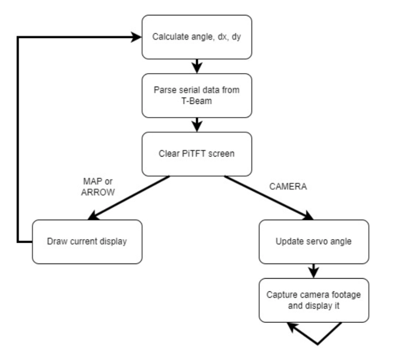
Pi Loop Flow
The following diagram shows how GPS from both T-Beams are communicated to the Pi for the dx, dy, and angle calculations described above. The red line represents location data from the external T-Beam. The blue arrow represents location data for the local T-Beam. The arrow between the two T-Beams is location data sent via the LoRa protocol. The first four bytes of each LoRa packet cannot be used for data, so dashes are used. The two arrows between the local T-Beam and Pi are communicated via a serial connection. The location data for the local T-Beam is differentiated by adding a ‘P’. The dashes are helpful because it allows latitude and longitude to be efficiently parsed by splitting the data on the dashes.
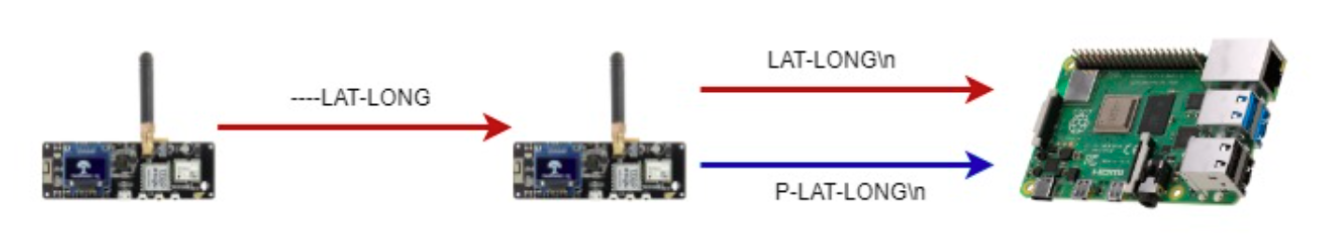
Serial and LoRa Packets
Our system also features a quit and shutdown button. The quit button is linked to GPIO pin 17. A callback is used to call sys.exit() if the button (located on the PiTFT) is pressed. The shutdown button works using dtoverlay gpio-shutdown with GPIO pin 27 (one of the PiTFT buttons). To shutdown the Pi, the quit button must be pressed first to exit the program.
Pi T-Beam Software Design
The local T-Beam is responsible for obtaining a GPS lock, listening for LoRa packets from the external T-Beam with its GPS data, and forwarding external T-Beam packets to the Pi via serial and forming packets with its GPS location data to send to the Pi via serial.
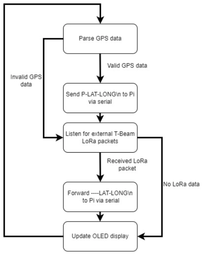
Local T-Beam Flow
T-Beam Software Design
The external T-Beam is responsible for obtaining a GPS lock and periodically (every 5 seconds) beaconing its longitude and latitude in a LoRa packet. The longitude and latitude are also displayed on an OLED display. Internally, the GPS is connected to the T-Beam processor using serial. The LoRa radio is connected via SPI. The power management unit is used to enable the LoRa and GPS units.

T-Beam with GPS Lock
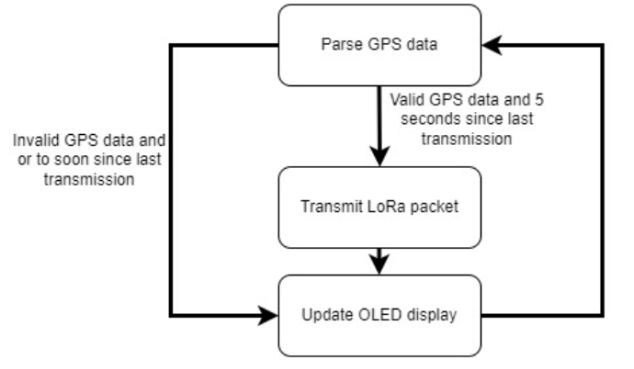
External T-Beam Flow
Pi Hardware Design
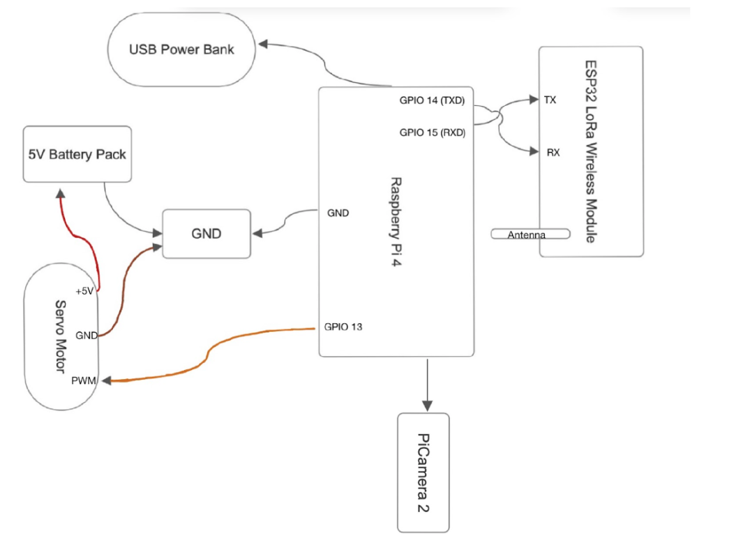
Schematic
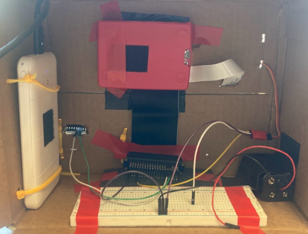
Final Design Wiring
The servo is powered by a 6V AA battery pack. The Pi is powered by a 5V USB power bank. The Pi supplies power to the camera and PiTFT. The T-Beam is powered by an 18650 battery. The camera communicates with the Pi via the MIPI camera serial interface protocol. The T-Beam uses serial at port /dev/ttyS0 to communicate with the Pi at 38400 bauds.
Testing
We incrementally tested our design, checking that each type of communication worked before moving forward. The Arduino IDE was used to develop and deploy code to the two T-Beams. The LEDs on the T-Beams were helpful for debugging. For example, the blinking red LED indicates that the GPS has a lock. The solid red LED indicates that the GPS unit is powered. The blue LED indicates that the LoRa radio was powered. Initially, the example code used to transmit LoRa packets for the T-Beam did not enable the LoRa module correctly due to the new kind of power unit used for T-Beam Meshtastic v1.1 vs 1.2. Version 1.2 uses power management circuit AXP2101, while 1.1 uses AXP192. Without accounting for this change, the blue LED on the T-Beam did not light up. The next step was to test that LoRa packets could be sent from the external T-Beam to the local T-Beam. This was tested by attempting to send LoRa packets in close proximity and debugging using a serial monitor. After this, the serial connection between the Pi and T-Beam was tested. Once the entire system was tested in the lab, we began moving the external T-Beam to ensure that dx, dy, and angle were calculated correctly. We added dx, dy, angle, and a counter to indicate the number of LoRa packets received to the PiTFT to help debug when testing. The conclusion section goes into more detail about the different locations the external T-Beam was placed for testing. We decided to add a compass to our design since all of the displays are relative to the North.
Results
Our initial final project idea was to use a RFM95W LoRa Radio connected to the Pi via SPI and a NEO-6M GPS connected to the Pi via serial in order to beacon LoRa packets and update the GUI in order to locate the T-Beam Meshtastic located a distance away. We were able to fully execute our initial idea and had a working prototype. The day before our final demo we completed a full run through with just slight servo motor issues when panning the camera to locate the T-Beam. To fix this we switched from the pigpio library to control external GPIO pins to PWM signals that would alter the duty cycle of our micro servo. We tested functionality and were able to map the angle readings to desired duty cycles of the servo motor using a formula we made via trial/error process. We used a power supply provided in the lab to supply power to the servo during our testing process. As we continued on with testing and fine tuning our project, we noticed that the NEO-6M GPS was not working so we re-checked wiring and tried to isolate it from the system to make sure it was not a trickle down issue. Continuing on with testing and adding back in the electrical components, we realized that smoke was coming from our project, and we ultimately fried everything in series with the Raspberry Pi. This meant that with less than 24 hours until our final demo, almost all of our essential electrical components alongside the fundamental Raspberry Pi and PiTFT were completely fried. With much thanks to the ECE 5725 faculty & staff we were able to hit the ground running with a new Raspberry Pi 4 and PiTFT. Luckily we had a spare T-Beam Meshtastic that we could use for our new project. Using the onboard GPS and LoRa Radio modules from the spare T-Beam Meshtastic we were able to keep the original objective of our project: finding the other T-Beam using LoRa packets. Now, the T-Beam Meshtastic connected serially to the Pi was able to send data packets to the other T-Beam placed at a distance away. Ultimately, we were able to have a fully functioning demo by our scheduled time. We appreciate the help and support we got through this unexpected process.
Conclusion
We were able to transmit location data from the external T-Beam (shown in red) from the top floor of the Rhodes stairwell to the Pi at various locations (the farthest locations are shown in the blue outlines). We double checked our dx, dy, and angle calculations at these locations by determining the actual longitude and latitude online. We scaled the MAP display for these locations. As shown in our demo, the ARROW view pointed towards the external T-Beam. The MAP view clearly showed the T-Beam icon moving away from the Pi’s current location as we walked away from the Rhodes stairwell. We found that the T-Beams had to have a line of sight to each other in order for packets to reliably be transmitted. Additionally, since we were using GPS, both devices had to be in view of the sky. The lack of range in the camera angle made it difficult for the servo to turn the camera towards the stairwell, but the video feed consistently updated as expected. In conclusion, we believe our system met project requirements by accurately displaying the relative location of the two modules.
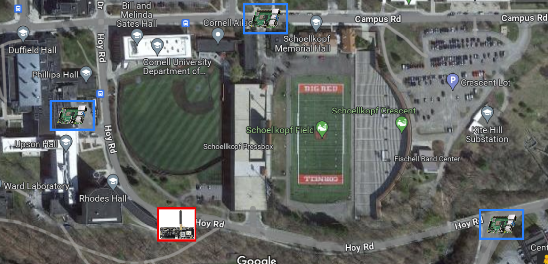
Testing Locations
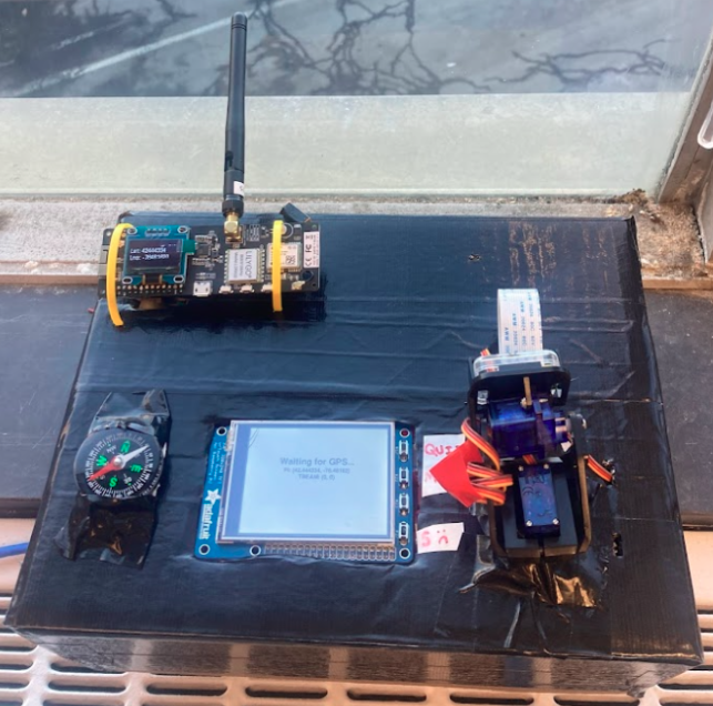
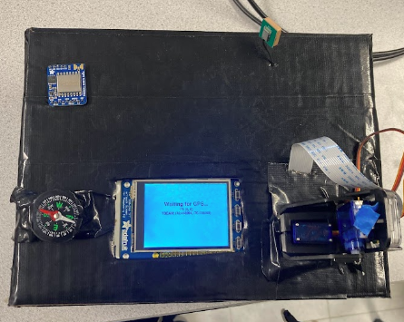
Final Pi Module Integration
Future Work
In the future, it would be interesting to see what the maximum distance between the two modules could be. Another experiment would see how fast the Pi embedded device could track the T-Beam (for example, if the T-Beam is placed in a traveling car, could the PiTFT still display an accurate position). We also found that turning the camera from -45 to 45 degrees was a small range. Wiring the camera so that it can turn 360 degrees would be more useful.
Work Distribution
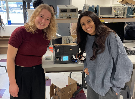
Project Group Picture

Lauren Greenhill
ljg227@cornell.edu
Lauren worked on the code for both T-Beams and the serial interface between the Pi and the local T-Beam as well as forming the LoRa packets between the two T-Beams. She also made the state machine to transition between different displays and programmed the start screen, map screen, and arrow screen. Lauren also configured the Pi to have shutdown and quit GPIO pins.

Veda Balte
vb269@cornell.edu
Veda worked on integrating the PiCamera and Servo Motors for the handheld Raspberry Pi module. She also worked on testing, edited the video and created the electrical schematic.
Parts List
- Raspberry Pi - Provided in lab
- PiTFT - Provided in lab
- Raspberry Pi Camera V2 - Provided in lab
- Servo Gimble - Provided in lab
- Servo Motor - Provided in lab
- USB Battery Pack - Provided in lab
- 6V Battery Pack - Provided in lab
- 18650 Battery - $5.00 x 2
- 915Mhz T-Beam Meshtastic - $33.30 x 2
- Compass - $4.99
- LEDs, Resistors and Wires - Provided in lab
Total: $81.59
References
- BearDrop T-Beam LoRa Code
- PiCamera2 Configuration
- PiCamera2 Data Sheet
- PiCamera2 Examples
- SG90-Pan
- PIGPIO Library for Servo Motors
- Servo Motor Movement
- PIRGB Array
- Shutdown Pin
- Mapping Range
- T-Beam LoRa Sender Code
- RFM95W LoRa Radio Tutorial
- Calculating Position
- Moving Servo
- Shutdown Button
- T-Beam v1.2
- T-Beam Serial
Code Appendix
main_loop_tbeam.py
import sys
import time
import os
import RPi.GPIO as GPIO
import pygame
import math
import pigpio
from pygame.locals import *
import serial
import io
import pynmea2
import adafruit_rfm9x
import busio
from digitalio import Pin, DigitalInOut
import board
from picamera import PiCamera
from picamera.array import PiRGBArray

# Display on piTFT
os.putenv('SDL_VIDEODRIVER', 'fbcon')
os.putenv('SDL_FBDEV', '/dev/fb0')

#Initialize PyGame and GUI Images
pygame.init()
pi    = pygame.image.load("/home/pi/final/pi.png")
tbeam = pygame.image.load("/home/pi/final/tbeam.png")
arrow = pygame.image.load("/home/pi/final/arrow.png")

# piTFT display values
size = width, height = 320, 240
WHITE = 255, 255, 255
BLACK = 0,0,0
RED = 255, 0, 0
BLUE = 0, 0, 255
FONT_SMALL = pygame.font.Font(None, 20)
FONT_LARGE = pygame.font.Font(None, 30)

# piTFT GPIO button values
QUIT         = 17
CHANGE_VIEW  = 22

#SERVO GPIO Button Value
SERVO = 13

# screen modes
START  = -1
MAP    = 0
CAMERA = 1
ARROW  = 2

# global variables
screen_mode = START
pi_lat = 0
tbeam_lat = 0
pi_long = 0
tbeam_long = 0
new_angle = 0
old_angle = 0
dx = 0
dy = 0
last_packet = 0

# T-Beam serial
ser = serial.Serial('/dev/ttyS0', 38400, timeout=1)
sio = io.TextIOWrapper(io.BufferedRWPair(ser,ser))

# Camera
camera = PiCamera()
camera.resolution = (320, 240)
camera.framerate = 24
rawCapture = PiRGBArray(camera, size=(320, 240))

#PyGame Display
screen = pygame.display.set_mode(size)
pygame.mouse.set_visible(False)

#Set GPIO
GPIO.setmode(GPIO.BCM)

# piTFT buttons
GPIO.setup(QUIT,        GPIO.IN, pull_up_down=GPIO.PUD_UP)
GPIO.setup(CHANGE_VIEW, GPIO.IN, pull_up_down=GPIO.PUD_UP)

#SERVO
GPIO.setup(SERVO, GPIO.OUT)
servo = GPIO.PWM(SERVO, 50)
servo.start(0)

#Quit Program
def QUIT_callback(channel):
    sys.exit()
GPIO.add_event_detect(QUIT, GPIO.FALLING, callback=QUIT_callback, bouncetime=300)

#Switch GUI View
def CHANGE_VIEW_callback(channel):
    print("!!CHANGE VIEW!!")
    global screen_mode
    if(screen_mode != START):
        screen_mode = screen_mode + 1
        if ( screen_mode == 3 ):
            screen_mode = 0
GPIO.add_event_detect(CHANGE_VIEW, GPIO.FALLING, callback=CHANGE_VIEW_callback, bouncetime=300)

#Function to Translate Ranges
def map_range(angle, in_min, in_max, out_min, out_max):
    return ( (angle - in_min) * (out_max - out_min)) / (in_max - in_min) + out_min

#convert angle to duty cycle
def calc_duty_cycle(angle):
    if (angle == 0):
        return 0
    return ( (1/30) * angle ) + 4.5

start_time = time.time()

#Calculate and print dx, dy, and angle
while(True):
    print("dx: " + str(dx))
    print("dy: " + str(dy))
    print("angle: " + str(new_angle))

    dlong = tbeam_long - pi_long
    raw_dx = math.cos(tbeam_lat) * dlong
    raw_dy = math.cos(pi_lat) * math.sin(tbeam_lat) - math.sin(pi_lat) * math.cos(tbeam_lat) * math.cos(dlong)

    print("raw dx: " + str(raw_dx))
    print("raw dy" + str(raw_dy))

    dy = map_range(raw_dy, -.005, .005, -height/2, height/2)
    dx = map_range(raw_dx, -.005, .005, -width/2, width/2)
    new_angle = math.degrees(math.atan2(raw_dx, raw_dy))

    #parsing packets
    try:
        packet_text = str(ser.readline())
        data = packet_text.split("-")
        if (packet_text[2] == 'P'):
            print(data)
            if(data[1] != '' and data[-1][:-3] != ''):
                pi_lat = float(data[1])/1000000
                pi_long = -1*float(data[-1])/1000000
        else:
            print(data)
            if(len(data) >= 5 and data[4] != '' and data[-1][:-3] != ''):
                tbeam_lat = float(data[4])/1000000
                tbeam_long = -1*float(data[-1])/1000000
                last_packet = last_packet + 1
    except ValueError:
            print("value error")

    screen.fill(WHITE)

    # piTFT display
    if( screen_mode == START ):
        text = FONT_LARGE.render("Waiting for GPS...", True, BLACK)
        screen.blit(text, text.get_rect(center=(160, 80)))
        text = FONT_SMALL.render("PI: (" + str(pi_lat) + ", " + str(pi_long) + ")", True, BLACK)
        screen.blit(text, text.get_rect(center=(160, 100)))
        text = FONT_SMALL.render("TBEAM: (" + str(tbeam_lat) + ", " + str(tbeam_long) + ")", True, BLACK)
        screen.blit(text, text.get_rect(center=(160, 115)))
        if ( pi_lat != 0 and pi_long != 0 and tbeam_lat != 0 and tbeam_long != 0 ):
            screen_mode = MAP
    # Map
    elif ( screen_mode == MAP ):
        pirect = pi.get_rect(center=(int(width/2), int(height/2)))
        tbeamrect = tbeam.get_rect(center=(int(dx+(width/2)),int((height/2)-dy))) # will be position based on GPS
        text = FONT_SMALL.render("dx: " + "{:.4f}".format(dx) + ", dy: " + "{:.4f}".format(dy) + ", angle: " + "{:.4f}".format(new_angle) + ", " + str(last_packet), True, BLACK)
        screen.blit(text, text.get_rect(center=(170, 230)))
        screen.blit(pi, pirect)
        screen.blit(tbeam, tbeamrect)

    # Camera
    elif ( screen_mode == CAMERA ):
        surface = pygame.display.set_mode([320, 240])

        # Create a loop to continuously display the video feed
        for frame in camera.capture_continuous(rawCapture, format='bgr', use_video_port=True):
            # Capture a frame from the camera
            image = frame.array

            rawCapture.truncate(0)
            if( screen_mode != CAMERA ):
                break

            # Convert the image to a Pygame surface
            surf = pygame.image.frombuffer(image, (320, 240), 'RGB')

            # Display the surface on the screen
            surface.blit(surf, (0, 0))

            # Update the display
            pygame.display.update()

        if(new_angle != old_angle):
            # north is 45 degrees (starting position)
            servo_angle = calc_duty_cycle(map_range(-old_angle, -180, 180, -45, 45))

            servo.ChangeDutyCycle(servo_angle)
            time.sleep(0.3)
            servo.ChangeDutyCycle(0)

            servo_angle = calc_duty_cycle(map_range(new_angle, -180, 180, -45, 45))

            servo.ChangeDutyCycle(servo_angle)
            time.sleep(0.5)
            servo.ChangeDutyCycle(0)

            old_angle=new_angle
            rawCapture.truncate(0)
    #Arrow
    elif ( screen_mode == ARROW ):
        arrow = pygame.image.load("/home/pi/final/arrow.png")
        arrow = pygame.transform.rotate(arrow, new_angle)
        text = FONT_SMALL.render("dx: " + "{:.4f}".format(dx) + ", dy: " + "{:.4f}".format(dy) + ", angle: " + "{:.4f}".format(new_angle) + ", " + str(last_packet), True, BLACK)
        screen.blit(text, text.get_rect(center=(170, 230)))
        text = FONT_LARGE.render("N", True, BLACK)
        screen.blit(text, text.get_rect(center=(width/2, 10)))
        screen.blit(arrow, (width/2 - 25,height/2 - 25))

    pygame.display.flip()

GPIO.cleanup()
startup.sh
sudo systemctl stop serial-getty@ttyS0.service
sudo python /home/pi/final/main_loop_tbeam.py
tbeam_pi.ino
// Adapted from https://github.com/Xinyuan-LilyGO/LilyGo-LoRa-Series/tree/master/examples/ArduinoLoRa/LoRaSender
#include <LoRa.h>
#include <TinyGPS++.h>
#include "boards.h"

TinyGPSPlus GPS;
HardwareSerial GPSSerial(1);

int32_t Lat = 0;
int32_t Lng = 0;
unsigned long timeSent = 0;

void setup()
{
    initBoard();
    // When the power is turned on, a delay is required.
    delay(1500);

    //GPS
    GPSSerial.begin(9600, SERIAL_8N1, 34, 12);

    // Pi
    Serial2.begin(38400, SERIAL_8N1, 13, 14);

    // LoRa
    LoRa.setPins(RADIO_CS_PIN, RADIO_RST_PIN, RADIO_DIO0_PIN);
    if (!LoRa.begin(LoRa_frequency)) {
        Serial.println("Starting LoRa failed!");
        while (1);
    }
}

void loop()
{
    if (GPSSerial.available()) {
      char c = GPSSerial.read();
      Serial.print(c);
      GPS.encode(c);
      Lat = GPS.location.lat() * 1E6;
      Lng = GPS.location.lng() * 1E6;
    }

    // Write Pi coordinates (from local GPS module) pi_lat pi_long
    if(GPS.location.isValid()){
      char msg[256];
      snprintf(msg, sizeof(msg), "P-%d-%d\n", Lat, Lng);
      Serial.print(msg);
      Serial2.write(msg);
    }

    int packetSize = LoRa.parsePacket();
    if (packetSize) {
      // received a packet
      Serial.print("Received packet '");

      char msg[256];
      int i = 0;
      while (LoRa.available() && i < 256) {
        msg[i] = (char)LoRa.read();
        i = i + 1;
      }
      msg[i] = '\n';

      // Write T-Beam coordinates (from LoRa message) tbeam_lat tbeam_long
      Serial.print(msg);
      Serial2.write(msg);
    }

#ifdef HAS_DISPLAY
    if (u8g2) {
        char buf[256];
        u8g2->clearBuffer();
        if(GPS.location.isValid()){
          u8g2->drawStr(0, 12, "Transmitting: OK!");
        } else {
          u8g2->drawStr(0, 12, "Waiting for GPS");
        }
        snprintf(buf, sizeof(buf), "Lat: %d", Lat);
        u8g2->drawStr(0, 30, buf);
        snprintf(buf, sizeof(buf), "Lng: %d", Lng);
        u8g2->drawStr(0, 48, buf);
        u8g2->sendBuffer();
    }
#endif
}
tbeam.ino
// Adapted From https://github.com/Xinyuan-LilyGO/LilyGo-LoRa-Series/tree/master/examples/ArduinoLoRa/LoRaSender
#include <LoRa.h>
#include <TinyGPS++.h>
#include "boards.h"

TinyGPSPlus GPS;
HardwareSerial GPSSerial(1);

int32_t Lat = 0;
int32_t Lng = 0;
unsigned long timeSent = 0;

void setup()
{
    initBoard();
    // When the power is turned on, a delay is required.
    delay(1500);

    //GPS
    GPSSerial.begin(9600, SERIAL_8N1, 34, 12);

    // LoRa
    LoRa.setPins(RADIO_CS_PIN, RADIO_RST_PIN, RADIO_DIO0_PIN);
    if (!LoRa.begin(LoRa_frequency)) {
        Serial.println("Starting LoRa failed!");
        while (1);
    }
}

void loop()
{
    if (GPSSerial.available()) {
      char c = GPSSerial.read();
      Serial.print(c);
      GPS.encode(c);
      Lat = GPS.location.lat() * 1E6;
      Lng = GPS.location.lng() * 1E6;
    }

    // send packet
    if(GPS.location.isValid() && ((millis() - timeSent) > 5000)) {
      Serial.println("Sending Packet");
      LoRa.beginPacket();
      LoRa.print("----"); // Preamble
      LoRa.print(Lat);
      LoRa.print("-");
      LoRa.print(Lng);
      LoRa.endPacket();
      timeSent = millis();
    }

#ifdef HAS_DISPLAY
    if (u8g2) {
        char buf[256];
        u8g2->clearBuffer();
        if(GPS.location.isValid()){
          u8g2->drawStr(0, 12, "Transmitting: OK!");
        } else {
          u8g2->drawStr(0, 12, "Waiting for GPS");
        }
        snprintf(buf, sizeof(buf), "Lat: %d", Lat);
        u8g2->drawStr(0, 30, buf);
        snprintf(buf, sizeof(buf), "Lng: %d", Lng);
        u8g2->drawStr(0, 48, buf);
        u8g2->sendBuffer();
    }
#endif
}